
What Is a VVT Solenoid and How Does It Work?

Learn what a VVT solenoid does, how it controls oil flow and cam timing, where it is located, how many your engine may have, and signs of a fault.


Quick Answer
A VVT solenoid is an electrically controlled oil valve in a variable valve timing system. The engine control module commands the solenoid to route pressurized engine oil to a camshaft phaser. The phaser then advances or retards camshaft timing to match engine speed and load. A VVT solenoid is also called an oil control valve, camshaft actuator solenoid, timing-control valve solenoid, or VCT solenoid on some vehicles.
Safety note: Let the engine cool before touching a VVT solenoid or nearby components. Keep dirt out of exposed oil passages, and do not apply battery voltage, probe terminals, or remove the solenoid unless the vehicle-specific service procedure permits it. Incorrect testing can damage the solenoid or engine control circuit.
What Does a VVT Solenoid Do?
Variable valve timing changes when the intake valves, exhaust valves, or both open and close in relation to crankshaft position. Instead of using one fixed camshaft setting for every operating condition, the system can adjust cam timing for smoother idle, useful torque, stronger high-speed breathing, fuel efficiency, and emissions control. The exact strategy depends on the engine.
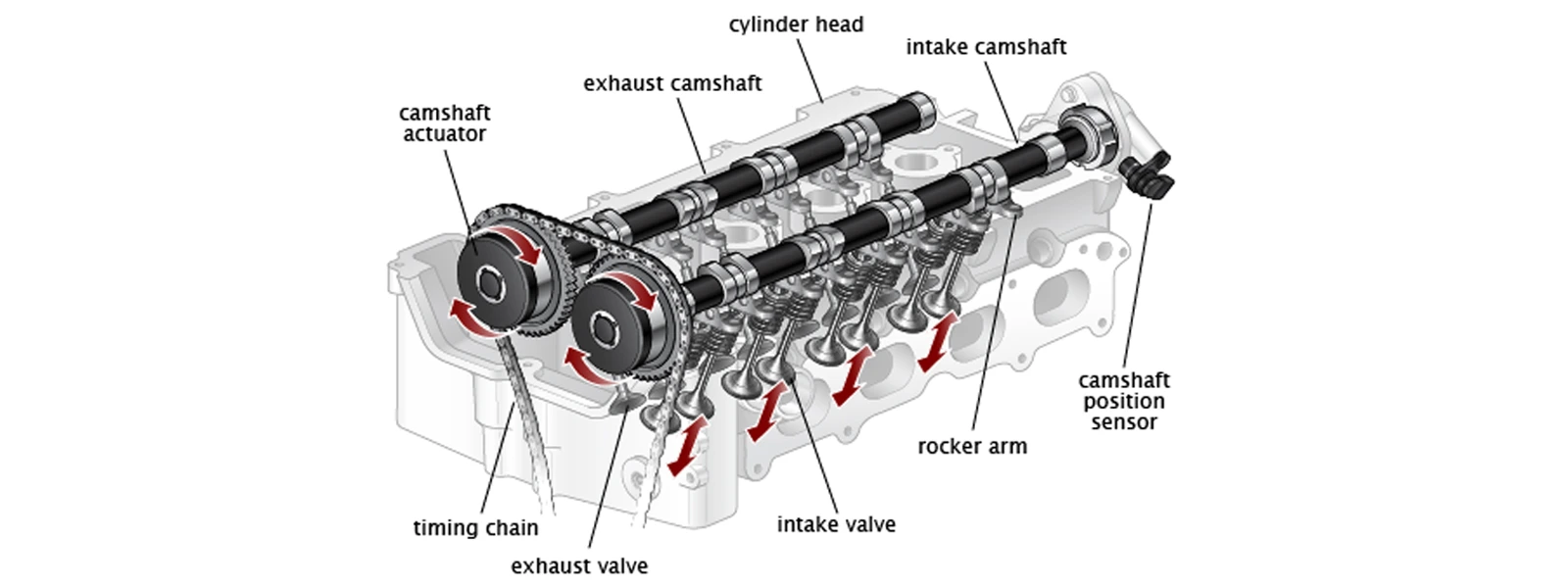
The VVT solenoid does not directly rotate the camshaft and it is not the same component as the camshaft phaser. It works as the system’s oil control valve. An electromagnetic coil moves an internal plunger or spool, opening and closing oil passages. That controlled oil pressure moves the phaser, and the phaser changes the camshaft’s angular position relative to its drive sprocket.
This distinction matters during diagnosis. A timing-related trouble code or rough-running symptom can result from the solenoid, but it can also come from low or contaminated oil, incorrect oil viscosity, restricted passages, damaged wiring, a camshaft position sensor problem, low oil pressure, a worn phaser, or a mechanical timing issue.
How Does a VVT Solenoid Work?
The system combines electronic control with hydraulic force. Although manufacturers use different names and calibrations, a common operating chain looks like this:
- The PCM or ECU calculates desired cam timing. It considers inputs such as engine speed, load, throttle position, temperature, and camshaft and crankshaft position.
- The control module commands the VVT solenoid. Many systems use a pulse-width-modulated electrical signal rather than a simple full-on/full-off command.
- The solenoid moves its internal spool valve. This redirects pressurized engine oil through selected passages.
- Oil pressure acts on the camshaft phaser. The phaser rotates the camshaft slightly relative to the timing sprocket, advancing or retarding cam timing.
- Position sensors provide feedback. The control module compares commanded timing with actual camshaft position and continues adjusting the command.
| System element | Job in the VVT system |
|---|---|
| PCM/ECU | Calculates desired timing and commands the solenoid |
| VVT solenoid / oil control valve | Meters and routes pressurized engine oil |
| Camshaft phaser | Uses oil pressure to change camshaft phase |
| Camshaft/crankshaft sensors | Report actual shaft positions for closed-loop control |
Because engine oil is the hydraulic working fluid, oil level, condition, pressure, viscosity, and passage cleanliness directly affect VVT operation. An electrically healthy solenoid cannot produce correct cam movement if the oil supply or mechanical phaser has a problem.
Where Is the VVT Solenoid Located?
A VVT solenoid is usually mounted in the cylinder head or near the top/front of the engine, close to the camshaft phaser and oil passages it controls. It commonly has an electrical connector, a cylindrical valve body that enters the cylinder head, one or more sealing O-rings, and a small retaining bolt or flange. Some designs use an external spool-valve assembly with a screen and gasket.
There is no universal location. It may sit beside the valve cover, at the timing-chain end of the cylinder head, under an engine cover, or beneath an intake component. On a transverse V6 engine, one bank may be easy to see while the other is close to the firewall. The words Bank 1, Bank 2, intake, and exhaust describe different positions and cannot be assigned from appearance alone.
How to identify the correct solenoid
- Use the year, make, model, engine size, and VIN when available.
- Check the under-hood emissions label and vehicle service information for the exact engine.
- Match the specified bank, intake/exhaust position, connector, mounting flange, oil ports, and part number.
- Do not assume two similar-looking solenoids are interchangeable.
How Many VVT Solenoids Does a Car Have?
A car may have one, two, three, four, or more VVT control solenoids depending on engine layout and how many camshafts are independently controlled. The number of cylinders alone does not determine the answer.
| Engine/VVT arrangement | Possible solenoid count | Why the count varies |
|---|---|---|
| Single-bank engine with one controlled cam | Often one | Only one cam circuit is varied |
| Single-bank dual VVT engine | Often two | Intake and exhaust cams are controlled separately |
| V-engine with VVT on both banks | Often two or four | Each bank, and sometimes each intake/exhaust cam, has its own control |
These are common arrangements, not fitment rules. Confirm the quantity and position through the parts catalog or service information for the exact engine. Replacing every solenoid because one circuit has a code is not automatically necessary.
What Are the Signs of a Bad VVT Solenoid?
A sticking or electrically faulty VVT solenoid can prevent actual cam timing from following the commanded position. Possible symptoms include a check engine light, rough idle, hesitation, reduced power, poor fuel economy, difficult starting, stalling, or abnormal engine noise. Symptoms vary with the camshaft, bank, failure position, and engine calibration.
Codes in families such as P0010, P0011, P0012, P0013, or P0014 may point toward a camshaft actuator circuit or timing-performance problem. They do not prove the VVT solenoid has failed. The code definition, freeze-frame data, and manufacturer’s diagnostic procedure must guide testing.
| Finding | Possible causes besides the solenoid | Useful next check |
|---|---|---|
| VVT performance code | Oil level/condition, restricted passage, low pressure, phaser, mechanical timing | Inspect oil and compare commanded versus actual cam timing |
| Circuit code | Open wire, short, poor terminal contact, control-module issue | Inspect connector and follow the specified circuit test |
| Rattle or timing noise | Low oil pressure, worn phaser, chain, guide, or tensioner problem | Stop and inspect mechanical timing if noise is severe |
See the full guide to bad VVT solenoid symptoms and diagnosis for a symptom-focused troubleshooting path.
How Do You Check a VVT Solenoid Before Replacing It?
Start with the checks that can reveal a system problem without condemning a part:
- Verify engine oil. Check level, condition, service history, and the viscosity required by the vehicle manufacturer. Correct an oil-pressure warning before further VVT testing.
- Scan all modules and record data. Save codes, freeze-frame information, and commanded versus actual camshaft angles when the scan tool supports them.
- Inspect the correct solenoid and circuit. Confirm bank and intake/exhaust position. Look for damaged wiring, oil in the connector, loose pins, corrosion, leaks, or a clogged external screen.
- Perform vehicle-specific electrical tests. Coil resistance, power supply, ground/control, duty cycle, and bidirectional actuation procedures differ by application. Use service-data specifications rather than a universal resistance value.
- Check the hydraulic and mechanical side. If the solenoid responds but cam timing does not, investigate oil passages, oil pressure, the phaser, sensors, and base mechanical timing.
Cleaning may help when a removable screen or spool is restricted by deposits and the manufacturer permits cleaning. It will not repair an open or shorted coil, damaged connector, worn valve bore, failed phaser, low oil pressure, or stretched timing chain. Avoid harsh solvents that can damage plastic, insulation, seals, or coatings.
If the oil-pressure warning is on, the engine has a severe timing rattle, the check engine light is flashing, or the engine stalls in traffic, stop driving and arrange diagnosis. Continuing to operate an engine with an oil-pressure or mechanical timing problem can cause much greater damage than a failed control valve alone.
How Do You Choose the Correct Replacement VVT Solenoid?
Replace the solenoid only after the fault has been isolated. Then match more than the component’s appearance. The correct part must fit the exact engine and the specified bank and camshaft position. Intake and exhaust VVT solenoids may use different oil-port layouts, flow calibration, connectors, or mounting features even when their housings look similar.
Before ordering, verify:
- Year, make, model, engine, and VIN-dependent production details
- Bank 1 or Bank 2 and intake or exhaust location
- Connector shape, terminal count, mounting flange, overall length, and oil-port design
- Whether the seal, screen, spool-valve housing, or mounting hardware is included
- Original-equipment and interchange numbers when available
For installation planning, follow the vehicle-specific procedure in this guide to replace a variable valve timing solenoid. If diagnosis confirms the part has failed, browse A-Premium timing-control valve solenoids and enter your vehicle before selecting a position-specific replacement.
FAQs
Is a VVT solenoid the same as an oil control valve?
Often, yes. Oil control valve, camshaft actuator solenoid, timing-control valve solenoid, and VVT solenoid commonly describe the electrically controlled valve that routes oil to a cam phaser. Confirm the manufacturer’s terminology for your engine.
Is a VCT solenoid the same as a VVT solenoid?
VCT means variable camshaft timing and is commonly used for the same general function. The name does not make parts interchangeable; fitment and position still matter.
Are intake and exhaust VVT solenoids the same?
Not necessarily. Some applications share a part, while others use different flow calibration, connectors, or port arrangements. Verify the catalog position before swapping or ordering.
Can low or dirty oil cause a VVT solenoid code?
Yes. VVT systems depend on clean oil at the correct level, viscosity, and pressure. Oil problems or restricted passages can prevent cam timing from responding even when the solenoid is electrically functional.
Can you drive with a bad VVT solenoid?
A vehicle may still run, but drivability and risk depend on the actual cause. Stop driving for an oil-pressure warning, severe rattle, flashing check engine light, repeated stalling, or major power loss.
Does a VVT code mean the solenoid must be replaced?
No. A code identifies a circuit or performance condition, not a confirmed failed part. Check oil, wiring, sensor data, oil pressure, the phaser, and mechanical timing as required by the diagnostic procedure.


